PreHEAT Installation GuideEN version: Craig Kulesa, Zhang Xu-Guo, Nick TothillCN version: Zhang Xu-Guo Link to the Chinese translations of the Hardware Installation Guide and the Software Guide 22 November 2007 |

|
PreHEAT Installation GuideEN version: Craig Kulesa, Zhang Xu-Guo, Nick TothillCN version: Zhang Xu-Guo Link to the Chinese translations of the Hardware Installation Guide and the Software Guide 22 November 2007 |
|
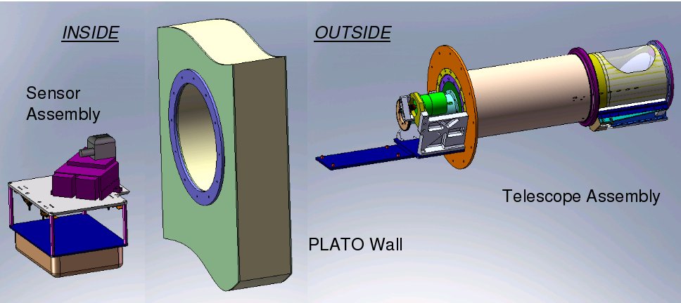
PreHEAT is a 0.2-meter submillimeter-wave telescope designed for autonomous operation at Dome A, the summit of the Antarctic ice plateau. PreHEAT is equipped with a 661 GHz (450 micron) Schottky diode receiver system, IF processor, total IF power detector, and digital FFT spectrometer. It is designed to perform submillimeter site testing, precipitable water vapor measurements, and molecular spectral line maps of 13CO J=6-5 in the plane of our Milky Way Galaxy. It is the technological forerunner to HEAT, the High Elevation Antarctic Telescope, which will be a 0.6-meter Terahertz telescope to be deployed to Dome A in late 2009.
|
|
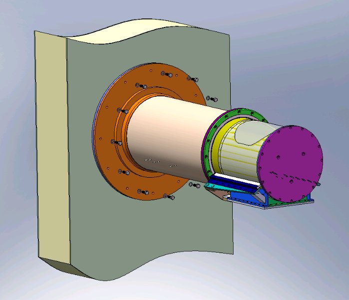
The telescope mounts to PLATO using twelve (12) M8 screws with a socket-type head. You will want 5 people available for the installation: 4 outside to lift the telescope and 1 person inside to guide the telescope in. You could do it with fewer people, but it is a good idea to have an extra person available "just in case".
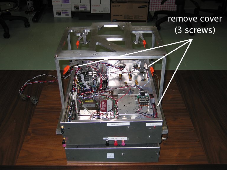
Careful! Do not lift telescope by motor or by the inner tube (with the window).| Unpack the electronics box. Shake the box gently and listen for any loose parts. Open the (top) electronics box by removing the top three screws. You will need a large flat-head screwdriver. |
|
|
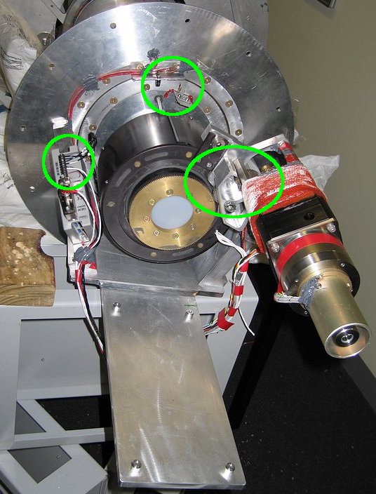
Inspect the inside of the box. Please inspect the connectors shown by
yellow squares and the power and data
connections shown by green circles. For
example, is the computer's 8 GB CompactFlash card fully inserted? Are the
vertical electronics board screws attached? Are the wires at the power
distribution terminal blocks secure?
Careful: Use static protection!! |

|
| Finally, inspect the telescope drive system. Are the motor controller wires tightly seated? Use a small flat-head screwdriver to tighten the screws. Do the drive gears mesh? Check alignment of the magnetic home sensor. |
|
|
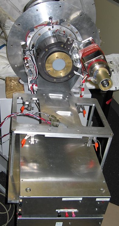
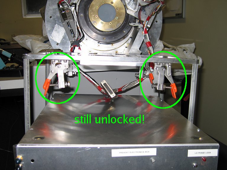
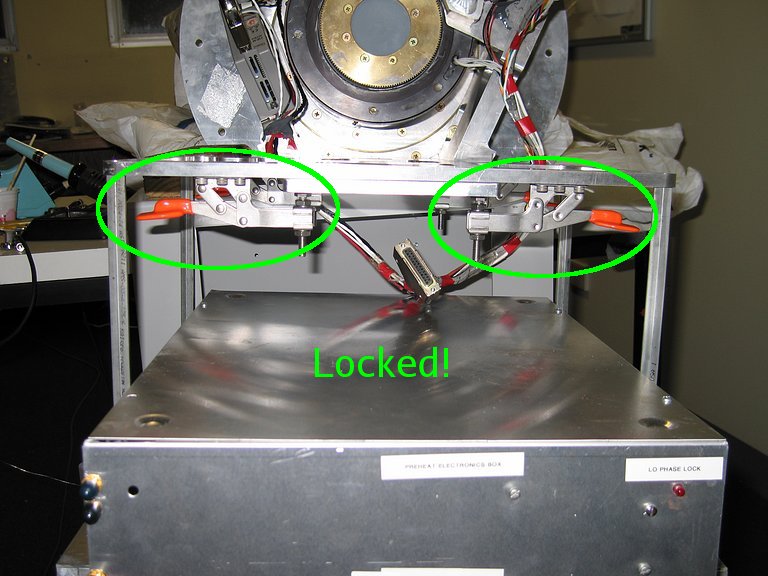
Re-install the top cover on the Electronics Box. Install the electronics box module onto the PreHEAT "tongue" and lock it into place with the clamps, as shown here. |
|
|
|
| Unpack the receiver module, remove the two (2) pieces of tape covering the receiver and LO feedhorns, and the foam+tape covering the tiny electronics board on the side of the aluminum block. Install it onto the mount. Bolt it down with the three (3) screws. The receiver should be slid as far forward as possible (however be sure that the receiver will not hit the telescope drive gear!). Also... do not forget the shim washer as shown in the photograph. |

|
| Use anti-static protection! Remove the protective metal cover from the Fabry-Perot Interferometer. Also remove the two pieces of copper tape that cover the small feedhorns on the Schottky receiver and Local Oscillator. Make note of the interferometer adjustment micrometer. We will need this later. |

|
| Use anti-static protection! Connect all cables to the front of the electronics box. Be sure to use only cables that belong to PreHEAT. You will connect a power cable, the telescope cable, and an ethernet cable. |

|
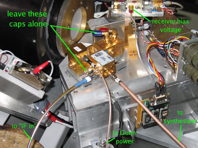
| Use anti-static protection! Connect the two (2) wire harnesses with milspec connectors from the electronics box to the receiver. Also connect the six (6) coaxial cables with SMA connectors. One (1) of them is attached to the receiver and supplies the receiver bias voltage. Three (3) of them connect the Local Oscillator (LO) to the Electronics Box, as shown here. Make sure that they are all correctly connected!! | |

|
|
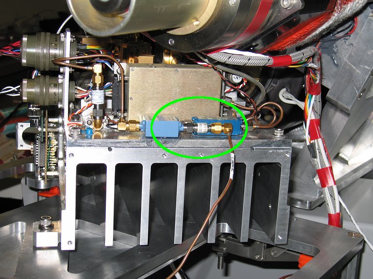
| The fifth (5) SMA cable is very rigid and has four (4) attenuators attached to it. One is on the receiver end, and the others are attached to the IF Processor box at the connector labeled CH3 IN. The last cable is short and connects the IF Processor connector labeled CH3 OUT to the top spectrometer port. | |
|

|
ssh obs@preheat
or
ssh root@preheat
rdate -a super1 || rdate -a super2 || rdate -a super3
You can close the telnet session with control-] and then q.
phaselock
At the conclusion of the phaselock command, the red LED on the electronics box labeled "phase lock" should light.
The final task is the optical alignment of the Schottky receiver to its Local Oscillator (LO). For this, you will need to bias up the Schottky receiver manually:
telnet preheat 9001
switchbias 0
setbias 0 10
setbias 1 11
Now read out the total power detected by the receiver:
setmux 0
readadc 0 8 10
The number returned is related to the total amount of Terahertz light the receiver is "seeing". Read the ADC a few times (typing the last command) and then put your (warm) hand in front of the plastic window and read the ADC again. The number should increase a little bit, since your hand is warmer (therefore brighter) than the cold Antarctic background.
|
Do you remember the
Fabry-Perot Interferometer? With the vibration of the
traverse, it is necessary to test the alignment of the
interferometer. Very carefully, and with very very small
adjustments, turn the interferometer micrometer and read the ADC
each time. The goal is to maximize the detected power. (If the number is
negative, try to make it go positive as best as you can).
To help you, there is a continuous read command: adccont. It will read the ADC repeatedly for 1 minute. |
|
When the total power detected by the receiver is maximized, you are done! Don't forget to close your telnet session.
Congratulations!